Flow carries heat, but it does not prove that radiators can release it or that a pump can overcome the circuit resistance. Check output, flow and head as separate linked questions.
1. Begin with room-by-room design heat loss
Use the applicable local heating-load method at the project outdoor design condition. A whole-house total helps size the heat source, while room loads determine where heat must be delivered.
Reflect insulation, airtightness and ventilation improvements before selecting emitters. Reusing an old boiler rating can preserve oversizing and says little about individual rooms.
2. Test emitters at the intended water temperatures
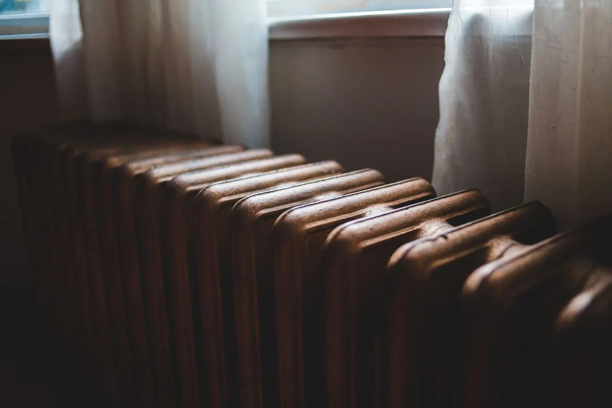
A radiator rating applies at stated water and room conditions. Lower mean water temperature reduces output substantially; use the manufacturer correction data when available or the calculator for an early screen.
Compare each room’s available emitter output with that room’s design loss. Do not rely only on the sum for the building because one cold room cannot borrow unused radiator surface from another.
3. Convert delivered heat into water flow
For water, required flow depends on heat carried and the supply-return temperature difference. A smaller temperature difference needs more flow for the same heat output.
Calculate the total and each branch at a consistent design condition. Antifreeze mixtures have different heat capacity and viscosity, so use appropriate fluid data when glycol is present.
4. Determine pump head from the hydraulic path
Flow rate does not determine pump head by itself. Head comes from pipe length and diameter, fittings, valves, emitters, manifolds and other components along the hydraulically most demanding active path.
Plot or verify the design duty point against the pump curve. Check minimum flow requirements, valve authority, noise risk and how variable-speed control behaves as zones open and close.
In a filled, closed loop, building height is not added as static lift to circulator head. Filling pressure and expansion protection remain separate design checks; open systems differ.
Caleffi · Closed-loop head and static pressure (North American design context) ↗5. Balance and verify the operating system
Have a qualified installer clean, fill, purge and balance the circuit and verify expansion and safety components. Record supply, return and room temperatures under representative demand.
A temperature difference is evidence, not a universal target. Interpret it together with flow, heat-source behaviour, emitter output and comfort. Recheck settings after the building has operated through stable cold weather.
Compare flow and temperature readings after operation has stabilized, not during initial warm-up; a single transient reading does not establish steady heat delivery.
Caleffi · Measuring circuit performance at steady state (North American design context) ↗Keep these design checks connected but distinct
| Question | Primary input | What it establishes |
|---|---|---|
| How much heat? | Room-by-room design losses | Required delivery |
| Can emitters release it? | Rated output and actual water temperatures | Available room output |
| How much water? | Heat and supply-return difference | Design flow |
| How much pump head? | Resistance of the critical path | Hydraulic duty point |
| Does it work? | Measured temperatures, flow and comfort | Commissioned performance |
Worked example
Screen a 6 kW circuit at 45/35°C
The circuit uses water and the rooms have already been checked individually.
Temperature difference = 45 − 35 = 10°C
Required flow = 6 × 60 / (4.186 × 10) = 8.6 L/min
A 1,500 W ΔT50 radiator at 45/35/20°C and n = 1.3 gives about 456 W
The flow estimate does not select a pump, and the radiator estimate must be compared room by room. Pipe resistance, balancing and manufacturer data remain separate checks.
What to have ready
- Room-by-room design heat losses
- Emitter data at the selected temperature regime
- Branch flows and critical-path pressure loss
- Pump curve, controls, balancing and measured commissioning data
Common mistakes
- Using the old boiler output as the building heat loss.
- Assuming a radiator retains its rated output at lower water temperature.
- Selecting a pump from flow alone without calculating circuit resistance.
Tools for these measurements
Prepare the measurements with these instrument guides.
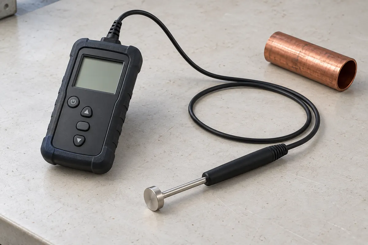
Check pipe or surface temperatures with an appropriate probe and recognize why surface temperature is not automatically water temperature.
How to use it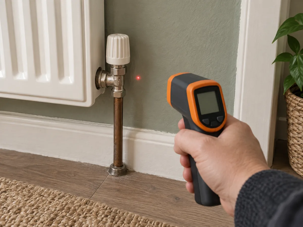
Check surface temperatures quickly and understand spot size, emissivity and reflective-surface errors.
How to use it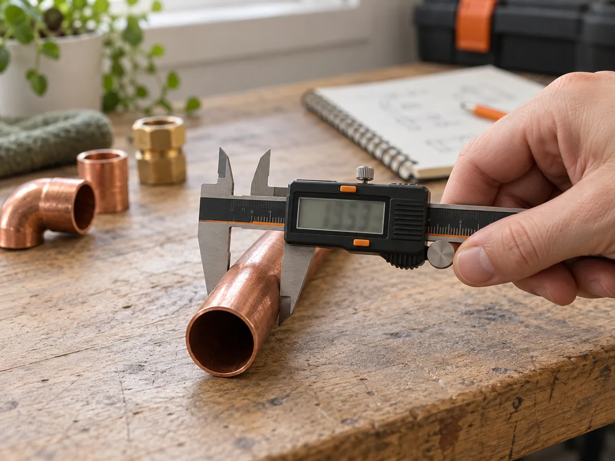
Measure outside, inside, depth and step dimensions without turning display precision into false accuracy.
How to use it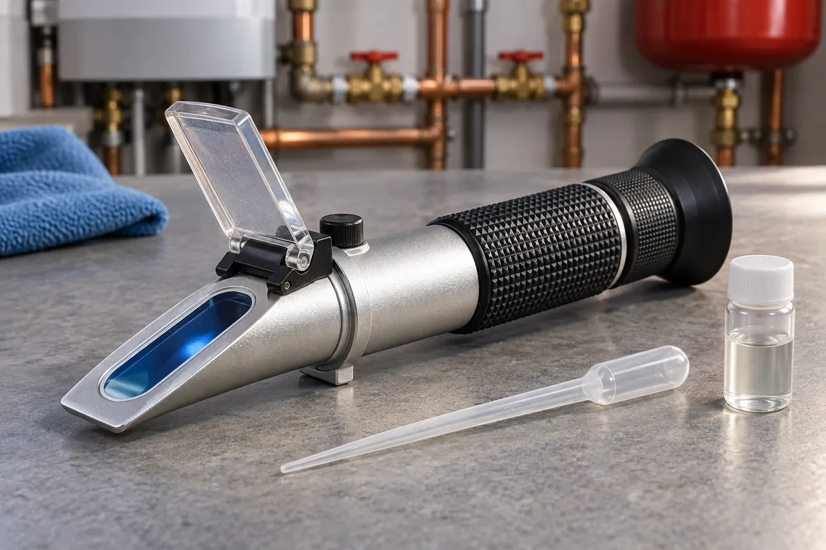
Check a known glycol sample with the correct scale; do not confuse concentration with a complete system-health assessment.
How to use itUse and limitations. Sources include US public agencies. Principles are general; regulations and design values must be checked where you live.Worked examples use stated hypothetical inputs.