A REPEATABLE METHOD
How to use it
- Define the outside dimension and mark the sample location and direction. Support the loose sample on a safe bench; choose a range and face shape that can reach it. Do not dismantle an installed assembly to obtain the sample.
- Inspect and clean the measuring faces and sample by their appropriate instructions. Check smooth movement within the stated range. Allow instrument and sample to settle in the same environment; avoid prolonged hand heating. Use the model manual, not an invented universal waiting time.
- Check the reference before measuring. A 0–25 mm instrument can be checked at closed faces; a 25–50 mm instrument needs the appropriate setting reference, not closed faces called zero. Keep reference checks separate from adjustment. An unexplained offset means stop and resolve it, not press ZERO or subtract it blindly. A single reference check is not full-range calibration.
- Approach gently with the sample correctly aligned between the faces. Use the model’s force-limiting device as instructed, not extra thimble torque or a universal number of clicks. Avoid trapping an edge or tilting the sample. Do not force a reading by squeezing soft material.
- Read the units and mode; view an analogue scale straight on. Release and repeat at the same marked location, then record other locations separately if relevant. Log instrument ID, range, reference check, surface condition and each reading. Recheck the reference if readings drift; clean and store by the manual, without forcing the faces shut.
INTERPRET THE MEASUREMENT
How to read the result
- Fictional metric scale: 0.5 mm travel per turn and 50 thimble divisions give 0.5 / 50 = 0.01 mm per division. If the last visible sleeve value is 7.5 mm and the aligned thimble mark is 23, the reading is 7.5 + 23 × 0.01 = 7.73 mm, not 7.23 or 7.523 mm. This assumes that scale design; do not apply it to every micrometer.
- Fictional digital repeats at one location: 7.731, 7.733 and 7.732 mm have a spread of 7.733 − 7.731 = 0.002 mm = 2 µm. A 0.001 mm display step equals 1 µm, not accuracy ±1 µm. Small spread does not prove closeness to the true dimension; do not average away a reference problem.
- A displayed 0.304 inch converts to 0.304 × 25.4 = 7.7216 mm. The conversion adds no measurement information: it does not establish four-decimal-place metric accuracy or exact agreement with 7.73 mm. Preserve the original reading and unit.
- Record separate sites as A and B rather than silently averaging thicknesses. A local reading includes the contacted surface or coating; it is not automatically bare-metal thickness. Several diameters alone do not certify roundness, and a nominal replacement size is not an acceptance tolerance.
TROUBLESHOOT THE METHOD
Common problems and what to check
The reference check has changed.
Stop using the readings for decisions. Check cleanliness, temperature, mode and the correct reference by the manual. If unexplained, arrange competent inspection; do not conceal the change with a convenient zero.
More force gives a smaller reading.
Do not tighten further. The sample, contact or technique may be unsuitable. Choose a suitable force/contact method rather than reporting the smallest number as correct.
The reading differs at different positions.
Retain each location and orientation. Surface shape, coating or setup may differ. Do not diagnose wear, certify a fit or choose a machining allowance from this observation alone.
STOP BEFORE THE HAZARD
Safety boundary
- Loose, cool, safely supported samples only. Never reach toward rotating machinery, hot parts, live equipment or stored-energy assemblies with the micrometer.
- Handle sharp sample edges and pinch points carefully. The instrument is not a clamp, marking tool or wrench; do not force travel beyond its range.
- After a drop or suspected damage, stop and obtain inspection. This page does not approve pressure-containing, structural, vehicle or other safety-critical parts or authorise machining or installation.
SMART BUYING GUIDE
What to look for when choosing
- Select range and access first; a 0–25 mm model cannot measure a 30 mm spacer. Check the actual model’s unit, scale and force mechanism.
- Match face geometry and force to the sample. Flat faces do not automatically measure a tube wall, a narrow groove or a soft gasket correctly.
- Look for documented accuracy, reference requirements and service support. Display digits and a zero button are not substitutes for calibration evidence or a suitable acceptance method.
Types of tool
Best for: Accessible rigid outside dimensions when the operator understands its particular sleeve and thimble scale.
Best for: Direct numeric recording with explicit unit/mode checks; the display does not remove contact and reference limitations.
Common functions
Worth paying more for
- The required range, sound measuring faces and a controlled-force mechanism.
- Documented specifications and appropriate reference/calibration support.
Usually not worth the extra cost
- Extra decimal places without a useful accuracy specification.
- Data output when a clear manual measurement record is sufficient.
Sources & instructions
- Mitutoyo Quick Guide: micrometer scales, contact mechanisms and temperature effects (English PDF, printed pages 6–8; design-specific examples)
- Mitutoyo Check Points: outside micrometer reference, handling and storage (English PDF, printed pages 1–2; follow the model manual)
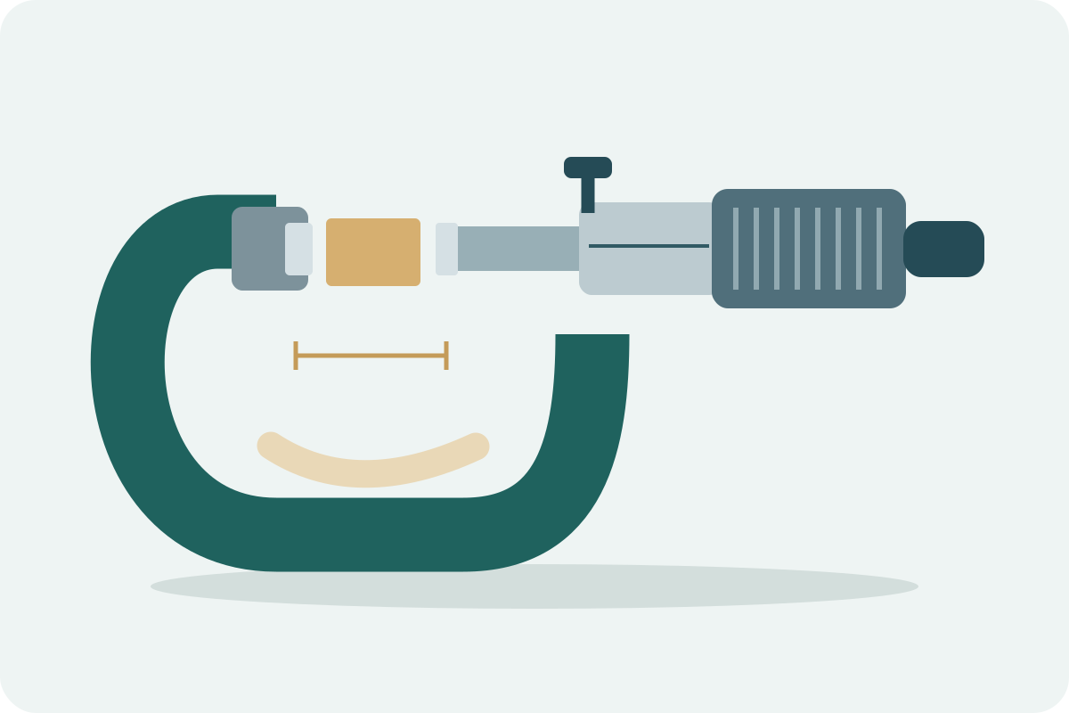
Original symbolic schematic, not a photograph, usable scale, calibration reference or dimensioned drawing. Shapes and clearances are not to scale.